Transformer Windings Explained: Common Winding Types and What to Look For
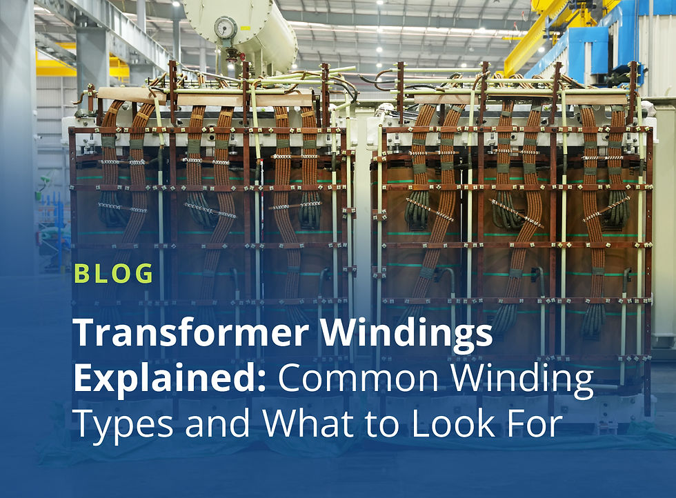
A transformer's windings set the voltage relationship between its two sides: whether the voltage steps up or down, and by how much. In most transformers, there are two or more coils of copper or aluminum wound around a shared core. The basic idea:
Alternating current flows into the primary coil (the input side) and creates a changing magnetic field.
The core channels that field to the secondary coil (the output side).
The ratio of turns between the two windings determines whether voltage steps up or down
How the conductor is wound then shapes the transformer's efficiency, short-circuit strength, cooling, and cost. Four winding types cover most of what you'll see in distribution and power transformers:
Foil
Helical
Layer (also called barrel)
Continuous disc
Here’s a quick guide to each main winding type and when to use them:
Foil Windings
Foil windings use thin sheets of copper or aluminum, wound in a continuous spiral with insulating material layered between each turn. This winding lends itself for use as the low voltage winding of many pad mounted transformers with voltages below 1000Vac due to its high current carrying ability.
Pros: Because the entire width of the conductor forms a single turn, foil windings distribute current evenly across the sheet.
This process largely eliminates the circulating currents that show up in windings built from multiple parallel strands.
Cons: A full-sheet conductor is harder to cool without well-designed ducting.
As a result, foil windings are generally reserved for lower-voltage coils, rather than the full winding stack.
When to Use: Foil windings are a strong fit for low-voltage, high-current applications, where a handful of conductors carrying heavy current would otherwise need careful transposition to stay balanced.
Helical Windings
Helical windings (also called screw or spiral windings) look rather like corkscrews. They’re built from multiple insulated conductor strands wound in parallel around the coil form, with one turn per axial position. Spacers separate adjacent turns to allow cooling oil to circulate.
Single-layer, double-layer, and multi-layer helical designs are all used, with the choice depending on current rating and available radial space.
Pros: Since each strand carries only a fraction of the total current, helical windings suit low-voltage, high-current applications.
Cons: The parallel strands need to be transposed periodically along the winding's length. Without transposition, the strands don't experience identical flux linkage, which creates unequal impedance between them and drives circulating-current losses.
When to Use: Low-voltage, high-current applications, typically in the range of 150 kVA to 30 MVA.
Layer (Barrel) Windings
Layer, or barrel, windings are built by winding conductor around a cylindrical or rectangular form from top to bottom, then reversing direction and winding back over the first layer. Vertical ducts between layers provide cooling paths.
Pros: Simpler, faster, and less expensive to build than disc designs; cools faster than foil windings
Cons: Layer windings handle impulse (surge) voltage less gracefully than disc windings. As voltage climbs, stress builds between adjacent layers, which is what limits layer construction to lower voltage classes. They also don't withstand short-circuit forces as well as disc designs do. This is why at 69kV dics windings take over and layer windings are no longer appropriate.
When to Use: The primary (higher-voltage) winding of medium-voltage distribution transformers rated up to 35 kV, where interlayer voltage stress stays within what standard insulation handles economically.
Continuous Disc Windings
Continuous disc windings are built from a series of flat coil sections (discs) stacked along the winding's axial length, with radial spacers between them for cooling and mechanical support.
Each disc is wound continuously from the previous one, without splicing, using a cross-over technique that alternates how each disc's turns are numbered (outside-in on one disc, inside-out on the next).
Pros: Discs can handle the higher short-circuit forces and impulse ratings associated with high-voltage transformers.
During a fault, the winding sees large radial and axial forces. Disc construction resists them well because each disc is a solid, rigidly supported section, with radial spacers and axial clamping that hold the winding in place and spread the load across the stack rather than letting it concentrate at any one point.
Cons: Disc windings cost more and take longer to build than layer designs.
When to Use: High-voltage transformers (69-550 kV). For power-class transformers, disc construction is the standard approach.
When to Use Each Winding Type
The right winding type depends on voltage class, current, and the application's short-circuit withstand capability.
Layer-wound designs: Medium-voltage distribution transformers up to 35 kV — lower cost, faster build times, and efficiency that holds up well within that range.
Helical and foil windings: Low-voltage, high-current coils, where current-splitting and even current distribution matter more than voltage class.
Continuous Disc Construction: 69+ kV, since the mechanical demands of a fault event at that voltage level exceed what layer-wound coils are built to withstand.
Final note: A transformer's design typically pairs multiple winding types across its primary and secondary coils. For maximum reliability and durability, ask your transformer supplier which combination of these coils will best suit your specific project.